
Introduction
GreenBug Energy has developed the following Fixed Speed Control Panels for our grid tied Archimedes screw generator systems.
Our Fixed Speed Induction Generator Controls Panels are designed for interconnection with the utility for either net metering or revenue producing applications such as Feed in Tariff programs.
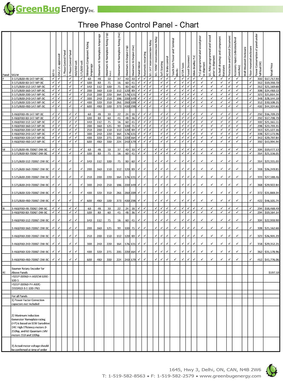
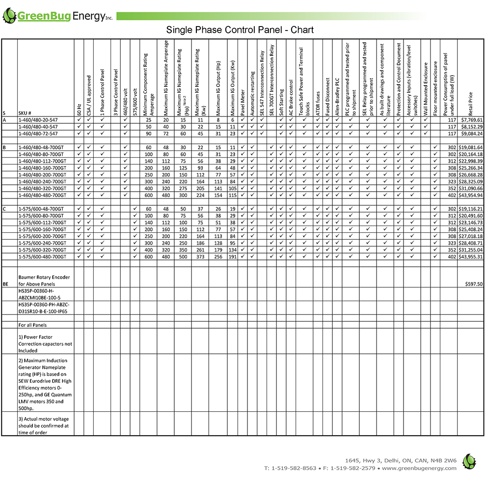
Panels are available in various combinations of 1 phase, 3 phase, 460/480 and 575/600 volt with SEL 547 and SEL 700GT protection schemes. Generator power out values from 1 to 191 kW single phase and 1 to 298 kW three phase.
All panels use 3 phase induction motors as a grid connected Induction Generator to produce either 1 or 3 phase power. Single phase induction motors cannot be used as generators. Three phase motors used to produce single phase power use run capacitors arranged to put the generator in a “balanced” condition.
Each of the panels ships with 1) a single line drawing and component list and 2) a Philosophy and Control Document. (in the door of the panel)
To find the panel you need faster, this is the way to interpret the SKU#:
- First number – is the phase, either 1 or 3 (and should match your service available )
- Second number – is the voltage of the control panel, either 460/480 or 575/600 (and should match your service voltage )
- Third number – is the Maximum Induction Generator Nameplate Amperage that the panel is designed for.
- Fourth number – is the protection relay the control panel uses, either SEL547 or SEL700GT. The SEL700GT provides additional protective features. (see below)
- Fifth number (applies to three phase panels only) – is Greenbug’s name for the protection scheme given the SEL relay that is being used. “MP” indicates voltage is being measured on two of the three phases using two current transformers. “DW” indicates voltage is being measured on all three of the three phases using two current transformers.
- Sixth number – (applies to three phase panels only) – “BC” indicates a Bypass Contactor is utilized. A Bypass Contactor is utilized so that power is not going through the SCR’s all the time. The SCR’s allow for soft starting of the generator, but after startup power is routed through the Bypass Contactor instead of through the SCR’s because the SCR’s consume a lot of power and they also produce a lot of heat.
To determine which control panel you need;
- Determine your generator size in kW or HP
- Next Determine your existing service size – phase/voltage/kVA – Generally, you want to use the biggest service voltage you can because it makes things cheaper, but if you have a service already you will want to use that service whatever phase and voltage it is as it will likely be cheaper than installing a new service. However the generator kW size will likely have to be 80% of the transformer kVA size or less. If it’s not the existing service/transformer may have to be upgraded. For example if you have a 100kVA service total on three phases, the maximum system size the utility will likely let you connect is 80kW. If you have a 100kW system you want to connect, this would require upgrading of your transformer.
- Next Identify the chart below that corresponds to your service phase, either single or three phase
- Next Identify on that chart the panel type(s) that are built for your service voltage. There may be several. Ie Panel type “F” and panel type “M” are both built for 575/600 voltage.
- Next, for the Panel types identified above, search down the list of panels in the Maximum IG Output kW or HP column for the panel that just exceeds your generator size.
- If you only found one control panel that fits, this is your only option. However, if you found several control panels, then next decide which protection level you prefer or need.
- Now that you’ve selected your control panel, you want to ensure that when you purchase your generator, that the voltage of the generator is at least as high as the service voltage. Ie if your service voltage is 575, your generator voltage should be 575 or higher.
- Also when selecting your generator, you must check to ensure its maximum nameplate amperage does not exceed the Maximum IG Nameplate Amperage of the control panel you selected. If it does, you need to select either a different control panel or different motor. This is the reason for Note 2 on the panel lists. It is possible that motors other than the motors identified in Note 2 may have different maximum nameplate amperage ratings than the motors identified, and the control panels are built only to accommodate the certain maximum IG nameplate amperage identified on the sheets.

Features and Benefits
- Pre-engineered panels. Decrease project cost and risk by using panels that have already been designed and are widely accepted.
- Easy selection based on generator nameplate. Simple selection charts allow an end user to select the appropriate panel based on their requirements.
- 1 and 3 phase. Panels cover wide range of single and three phase applications.
- 460/480 and 575/600 volt. Panels cover widest range of standard voltages in North American 60 Hz environment.
- Automatic Restarting. Generator will restart on its own with no need to human intervention.
- Choice of SEL 547 or 700 GT protection schemes. Allows the user to select the most cost effective option for their project.
- Soft Starting. Ensures there is no shock to the distribution system in the event of a hard start, a problem often associated with fix bladed wind turbines.
- Panel Meter (display Volts, Amps, Frequency, Active Power and Apparent Power Reactive Power, Active Energy, Reactive Energy, Power Factor, Amp Demand, Apparent Power Demand, Active Power Demand, Maximum Amp Demand, Maximum Apparent Power Demand and Maximum Active Power Demand). Easily see the parameters of your generator.
- Auxiliary Brake Control. Allows a safety brake to be used on generator.
- Touch Safe Power Terminals. Keeps fingers and people safe when inside the panel.
- ADTR Fuses. Quality time delay fuses, allow for very short term peeks in amperage.
- Fused Disconnect. Fused to eliminate the need for an additional disconnect, and ensure power is removed from panel when door is open.
- PLC – Programmed and Tested Prior to Shipping. We build it we test it and make sure it works before you receive it. This saves time during local start-up and commissioning.
- SEL – Programmed and Tested Prior to Shipping. If you have not programmed one before you will be glad the work is done when you receive your panel.
- As Built drawings and component list. When panel is completed, as built drawings are supplied with panel as well as any and all component literature.
- Protection and Control Document. A document that you can provide to the utility so they can understand how the system operates.
- Accessory switches Inputs. Allows additional safety switches to be added to your generator.
Additional Information
Induction Generation Basics
The induction generator is a device that converts mechanical energy into electrical energy.
A grid tied induction generator also known as an asynchronous generator is a type of AC electrical generator that uses the principles of induction motors to produce electrical power. Any regular 3 phase AC asynchronous motor usually can be used as a generator without any internal modifications. Induction generators are most commonly used in applications such as pico, micro, and mini hydro power plants and wind turbines.
When an induction motor is connected to an excitation source (the utility) it is capable of operating as a motor or as a generator. If the shaft is allowed to rotate at a speed below synchronous, the machine will attempt to operate as a motor. If the speed of the shaft is driven above 1800 rpm (4 pole motor) the machine will start to export electricity. The prime mover (e.g. Water turbine, or wind turbine) provides the energy using renewable a fuel (wind or water) to force the generator past its slip rpm.
Frequency Control
An inherent feature of the asynchronous induction generator is that frequency is stabilized by the utility line frequency (50 or 60Hz depending which part of the world you live in). Magnetism required for generation is created in the generator by reactive current flowing into the circuit from the utility.
When this reactive current is present the rotor within the generator is said to be “magnetically locked” to the utility. As the actual rotor speed when generating “slips” forward and turns slightly faster than 1800 rpm the generator will follow the utility line frequency. Our grid tied generating system cannot generate independent of the distribution system. When grid utility power is lost, the generator stops producing electricity.
Voltage Control
Utility line voltage levels stabilize the voltage level from the induction generator. As the generator is very small in terms of the load (the grid) it is pushing against, voltages levels at the Point of Common Coupling will not be affected.
It is recommended having a slightly higher generator nameplate voltage then the service it is connecting to. For example a 480 volt generator should be used on a 460 volt electrical service. If a generator with a higher voltage rating is not available, stepping down the voltage with a transformer is another acceptable method. It is also recommend using only WYE (Star) wound motors as generators.
Power Factor Correction
The operation of the generator is such that a lagging power factor may be experienced at the PCC (Point of Common Coupling). Generally this is not a concern. Utilities (such as Hydro One in Ontario, Canada) do not require power factor correction on small induction machines less than 30kw in output capacity.
If necessary, power factor correction will be applied in the form of capacitance to raise the DG (Distributed Generation) facility’s power factor at the PCC to a level acceptable by the LDC (Local electric Distribution Company). Terminals for Power Factor Correction connection are provided in all panels with generator output larger than 30kw’s.
Additional Generator/Turbine Protection
Panels have input for various switched protection elements such as oil level switches, vibration and temperature switches. If a switch is opened the system will disconnect from the utility. Switches are not supplied with the panels. A generator circuit breaker is also standard on all panels.
Islanding Control
Grid and Generator protection are controlled by a CSA and UL certified Distributed Generation Interconnection Relay by Schweitzer Engineering Laboratories, model SEL-547 or SEL-700GT. The SEL relays meet Protection and Control Elements required by IEEE 1547. This relay monitors all aspects of frequency and voltage and will disconnect generator in the event of abnormal voltage levels, frequency levels sensed from the grid.
SEL 547 protective features
– Undervoltage Relay (27)
– Directional Power Relay (32)
– Overvoltage Relay (59)
– Over Frequency Relay (81O)
– Under Frequency Relay (81U)
SEL 700GT protective features
– Undervoltage Relay (27)
– Directional Power Relay (32)
– Directional Power Relay – Reactive Power (32R)
– Instantaneous Overcurrent Phase (50P)
– Instantaneous Overcurrent Ground (50G)
– AC Time Overcurrent Relay Phase (51P)
– AC Time Overcurrent Relay Ground (51G)
– Overvoltage Relay (59)
– Over Frequency Relay (81O)
– Under Frequency Relay (81U)
– Rate-of-change-of-frequency Relay (81R)
Certification and Design of Panel
The panels are designed as per IEEE 1547 and cover varying ranges of utility/generator protection from minimal to maximum interconnection protection. All Panels are made in Canada and are built to CSA and UL specifications and will bear a label as such. Standard Gravolply labels, standard wire labels and standard TEW wire in Canadian color code unless other color coding requested (USA Destin panels). Components included are AB, ABB, Hammond, Mersen, SEL, Enerpro, Powerex, Weidmuller, Omron and Schneider.
Programming and Testing
All panels are programmed and tested prior to shipment on an actual induction generator. Both the PLC and SEL Relay are programmed and tested. Basic (standard) programming provides automatic generator control (generator will self-start) and has additional inputs for mechanical safety switches. From startup the control panel can be stopped (stop push button) and manually restarted (start button) for system testing and manual control. In the event of a power failure the system will restart automatically.
Panel Drawings
Panel and Protection scheme drawings can be provided for all panels upon request. Ordered panels come complete with a Panel drawing, Control Schematics drawing, Firing Board drawing, SEL relay drawing, PLC drawing, and BOM (bill of materials) as well as backup PLC programming and SEL relay settings sheet. Panels are not supplied with programming cables for either the SEL Relay, or PLC. These can be purchased by you from SEL or Allen Bradley.
Shaft Speed Encoder – optional
Greenbug recommends the use of a preprogrammed Baumer Rotary shaft encoder for generator shaft speed communication with the Control Panel. This Rotary Shaft encoder has additional protection for over speed sensing as well as loss of encoder/encoder fault detection. For an 1800rpm generator application this encoder will still send signals during over speeds of up to 4x synchronous speed. Panels are preprogrammed for use only with this encoder. Other speed measuring devises may be used but additional programming charges would apply.
Brake Control
All panels have an electrical circuit for a mechanic brake. This AC power safety brake can be either generator mounted, or mounted in another location on your equipment. A brake is not included with the control panel and should be sized accordingly for your application.
Onsite Commissioning and Initial Start-up
Greenbug fully tests each panel before it is shipped to the end user. It is highly recommend that the end user have someone with adequate technical knowledge of PLC programming and electrical control systems for start-up or adjustment of programming. This can be done remotely however it is far more difficult than having a qualified individual on site. SEL relay settings are based on Hydro One Networks most recent Technical Interconnection requirements, but can be easily suited to local interconnection requirements.
HMI
These panels do not have a Human Machine Interface (HMI). Greenbug sells the same panels it uses on its own generators. Our systems are built to last, and the key to longevity and cost reduction is simplicity. HMI’s although pretty to look at, add another level of complexity to the equipment that is not warranted in most situations.